
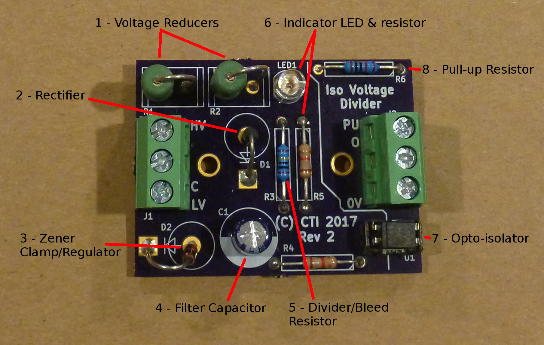
In working on various projects, I often need to interface signals to the input of an Arduino, Raspberry Pi, BeagleBone, or custom digital input. I wanted to be able to handle signals from 5V DC, 24V AC (sprinkler controller valves), up to 240V AC (to monitor my well pump run time). It needed optical isolation and an indicator LED to make it easy to see when a signal is active. I also wanted screw cage connectors so I did not not need to deal with crimping headers and larger wires can be used when monitoring a signal some distance away. So I put together a basic building block type circuit board that can be adopted to a wide range of uses. Below is a image of what it looks like. You can see it uses all through hole components. Since I will be using this in many different ways, I did not want to hassle with tracking down SMD components in the different values I will need. Also through hole makes it easy to change the values in the field when I am away from surface mount soldering tools.
If you just want to see how it works and make one yourself, here is the schematic. The values will vary and not all components are needed depending on the application.

I wrote up some application notes to keep track of the values and part numbers I have used.
https://docs.google.com/spreadsheets/d/1WZm22qj3Te460gnnhgaUxnhWV0CGRt9zXS8V44F-UMI/edit?usp=sharing
Or if this looks useful, I put the blank boards up for sale on Tindie:
https://www.tindie.com/products/conciseusa/isolated-wide-voltage-range-interface-board
Thank you! This looks exactly what I’m looking for. I want to monitor a multi-zone AC system which uses 24VAC with a Raspberry Pi. I was wondering though what pull up resistor would you use for a 3.3V application? Your spreadsheet says a 10K 1/4W, but I believe that’s for a 5V application? Couldn’t tell from your notes.
NM, I understand it’s application now after finding some diagrams of people tying optocouplers into a RasPI.